Google
 

Sunday, March 16, 2008

Fiber testing metre

The economical solution to help you save on today's costly testing operations this power meter tests both single mode and multi mode fibers quickly and accurately. And is very easy to use turn it on, select a wavelength and start testing. Hand held Power Meter measurements at 1310nm & 1550nm.

Technical Specification :
• Fiber certification with high accuracy and high resolution for both multi mode and single mode applications width 1310 nm or 1530 nm.
• Internal memory stores up to 1000 measurements and physical fiber characteristics for up to four sites.
• User friendly interface with alpha numeric membrane keypad for easy entry of testing documentation including site name, date, fiber type and length, connectors and splices.
• Lightweight and compact.
• Use the RS-232 interface and Windows® compatible OWL Reporter software to download data and print professional certificatio

Thursday, March 13, 2008

Repeater

A network device used to regenerate or replicate a signal. Repeaters are used in transmission systems to regenerate analog or digital signals distorted by transmission loss. Analog repeaters frequently can only amplify the signal while digital repeaters can reconstruct a signal to near its original quality.

In a data network, a repeater can relay messages between subnetworks that use different protocols or cable types. Hubs can operate as repeaters by relaying messages to all connected computers. A repeater cannot do the intelligent routing performed by bridges and routers.

Network repeaters regenerate incoming electrical, wireless or optical signals. With physical media like Ethernet or Wi-Fi, data transmissions can only span a limited distance before the quality of the signal degrades. Repeaters attempt to preserve signal integrity and extend the distance over which data can safely travel.

Actual network devices that serve as repeaters usually have some other name. Active hubs, for example, are repeaters. Active hubs are sometimes also called "multiport repeaters," but more commonly they are just "hubs." Other types of "passive hubs" are not repeaters. In Wi-Fi, access points function as repeaters only when operating in so-called "repeater mode."

Higher-level devices in the OSI model like and routers generally do not incorporate the functions of a repeater.

In telecommunication networks, a repeater is a device that receives a signal on an electromagnetic or optical transmission medium, amplifies the signal, and then retransmits it along the next leg of the medium. repeaters overcome the attenuation caused by free-space electromagnetic-field divergence or cable loss. A series of repeaters make possible the extension of a signal over a distance. In addition to strengthening the signal, repeaters also remove the noise or unwanted aspects of the signal.


Wednesday, March 12, 2008

ROUTER

A router is a device that forwards data packets along networks. A router is connected to at least two networks, commonly two LANs or WANs or a LAN and its ISP's network. Routers are located at gateways, the places where two or more networks connect, and are the critical device that keeps data flowing between networks and keeps the networks connected to the Internet. When data is sent between locations on one network or from one network to a second network the data is always seen and directed to the correct location by the router. They accomplish his by using headers and forwarding tables to determine the best path for forwarding the data packets, and they use protocols such as ICMP to communicate with each other and configure the best route between any two hosts.

The Internet itself is a global network connecting millions of computers and smaller networks — so you can see how crucial the role of a router is to our way of communicating and computing.

Why Would I Need a Router?
For most home users, they may want to set-up a LAN (local Area Network) or WLAN (wireless LAN) and connect all computers to the Internet without having to pay a full broadband subscription service to their ISP for each computer on the network. In many instances, an ISP will allow you to use a router and connect multiple computers to a single Internet connection and pay a nominal fee for each additional computer sharing the connection. This is when home users will want to look at smaller routers, often called broadband routers that enable two or more computers to share an Internet connection. Within a business or organization, you may need to connect multiple computers to the Internet, but also want to connect multiple private networks — and these are the types of functions a router is designed for.

Routers for Home & Small Business
Not all routers are created equal since their job will differ slightly from network to network. Additionally, you may look at a piece of hardware and not even realize it is a router. What defines a router is not its shape, color, size or manufacturer, but its job function of routing data packets between computers. A cable modem which routes data between your PC and your ISP can be considered a router. In its most basic form, a router could simply be one of two computers running the Windows 98 (or higher) operating system connected together using ICS (Internet Connection Sharing). In this scenario, the computer that is connected to the Internet is acting as the router for the second computer to obtain its Internet connection.

Going a step up from ICS, we have a category of hardware routers that are used to perform the same basic task as ICS, albeit with more features and functions. Often called broadband or Internet connection sharing routers, these routers allow you to share one Internet connection between multiple computers.

This image shows the flow of data to multiple computers sharing one high speed Internet connection.

Broadband or ICS routers will look a bit different depending on the manufacturer or brand, but wired routers are generally a small box-shaped hardware device with ports on the front or back into which you plug each computer, along with a port to plug in your broadband modem. These connection ports allow the router to do its job of routing the data packets between each of the the computers and the data going to and from the Internet.

Depending on the type of modem and Internet connection you have, you could also choose a router with phone or fax machine ports. A wired Ethernet broadband router will typically have a built-in Ethernet switch to allow for expansion. These routers also support NAT (network address translation), which allows all of your computers to share a single IP address on the Internet. Internet connection sharing routers will also provide users with much needed features such as an SPI firewall or serve as a a DHCP Server.

Wireless broadband routers look much the same as a wired router, with the obvious exception of the antenna on top, and the lack of cable running from the PCs to the router when it is all set up. Creating a wireless network adds a bit more security concerns as opposed to wired networks, but wireless broadband routers do have extra levels of embedded security. Along with the features found in wired routers, wireless routers also provide features relevant to wireless security such as Wi-Fi Protected Access (WPA) and wireless MAC address filtering. Additionally, most wireless routers can be configured for "invisible mode" so that your wireless network cannot be scanned by outside wireless clients. Wireless routers will often include ports for Ethernet connections as well. For those unfamiliar with WiFi and how it works, it is important to note that choosing a wireless router may mean you need to beef up your Wi-Fi knowledge-base. After a wireless network is established, you may possibly need to spend more time on monitoring and security than one would with a wired LAN.

Wired and wireless routers and the resulting network can claim pros and cons over each other, but they are somewhat equal overall in terms of function and performance. Both wired and wireless routers have high reliability and reasonably good security (without adding additional products). However —and this bears repeating — as we mentioned you may need to invest time in learning more about wireless security. Generally, going wired will be cheaper overall, but setting up the router and cabling in the computers is a bit more difficult than setting up the wireless network. Of course, mobility on a wired system is very limited while wireless offers outstanding mobility features.

A router is a device in computer networking that forwards data packets to their destinations, based on their addresses. The work a router does it called routing, which is somewhat like switching, but a router is different from a switch. The latter is simply a device to connect machines to form a LAN.

How a Router Works

When data packets are transmitted over a network (say the Internet), they move through many routers (because they pass through many networks) in their journey from the source machine to the destination machine. Routers work with IP packets, meaning that it works at the level of the IP protocol.

Each router keeps information about its neighbors (other routers in the same or other networks). This information includes the IP address and the cost, which is in terms of time, delay and other network considerations. This information is kept in a routing table, found in all routers.

When a packet of data arrives at a router, its header information is scrutinized by the router. Based on the destination and source IP addresses of the packet, the router decides which neighbor it will forward it to. It chooses the route with the least cost, and forwards the packet to the first router on that route.

Types of ROUTERS


Sunday, March 9, 2008

Twisted pair cable

Twisted pair cabling is a form of wiring in which two conductors are wound together for the purposes of canceling out electromagnetic interference (EMI) from external sources, electromagnetic radiation from the UTP cable, and crosstalk between neighboring pairs.

Twisting wires decreases interference because the loop area between the wires (which determines the magnetic coupling into the signal) is reduced. In balanced pair operation, the two wires typically carry equal and opposite signals (differential mode) which are combined by subtraction at the destination. The common-mode noise from the two wires (mostly) cancel each other in this subtraction because the two wires have similar amounts of EMI that are in phase. Differential mode also reduces electromagnetic radiation from the cable, along with the attenuation that it causes.

The twist rate (also called pitch of the twist, usually defined in twists per metre) makes up part of the specification for a given type of cable. Where pairs are not twisted, one member of the pair may be closer to the source than the other, and thus exposed to slightly different induced EMF.

Where twist rates are equal, the same conductors of different pairs may repeatedly lie next to each other, partially undoing the benefits of differential mode. For this reason it is commonly specified that, at least for cables containing small numbers of pairs, the twist rates must differ.

In contrast to FTP (foiled twisted pair) and STP (shielded twisted pair) cabling, UTP (unshielded twisted pair) cable is not surrounded by any shielding. It is the primary wire type for telephone usage and is very common for computer networking, especially as patch cables or temporary network connections due to the high flexibility of the cables.


Unshielded twisted pair (UTP)

Unshielded twisted pair cable.

Twisted pair cables were first used in telephone systems by Bell in 1881 and by 1900 the entire American network was twisted pair, or else open wire with similar arrangements to guard against interference. Most of the billions of conductor feet (millions of kilometres) of twisted pairs in the world are outdoors, owned by telephone companies, used for voice service, and only handled or even seen by telephone workers. The majority of data or Internet connections use those wires.

UTP cables are not shielded. This lack of shielding results in a high degree of flexibility as well as rugged durability. UTP cables are found in many ethernet networks and telephone systems. For indoor telephone applications, UTP is often grouped into sets of 25 pairs according to a standard 25-pair color code originally developed by AT&T. A typical subset of these AD1L colors (white/blue, blue/white, white/orange, orange/white) shows up in most UTP cables.

For urban outdoor telephone cables containing hundreds or thousands of pairs, different twist rates for each pair are impractical. For this design, the cable is divided into smaller but identical bundles, with each bundle consisting of twisted pairs that have different twist rates. The bundles are in turn twisted together to make up the cable. Because they reside in different bundles, twisted pairs having the same twist rate are shielded by physical separation. Still, pairs having the same twist rate within the cable will have greater crosstalk than pairs of different twist rate. Thus to minimize crosstalk within a large cable, careful pair selection is important. Twisted pair cabling is often used in data networks for short and medium length connections because of its relatively lower costs compared to fiber and coaxial cabling.

Uses

Unshielded twisted pair (UTP) cabling, because of its 100-year history of use by telephone systems, both indoors and out, is also the most common cable used in computer networking. It is a variant of twisted pair cabling. UTP cables are often called ethernet cables after Ethernet, the most common data networking standard that utilizes UTP cables.

Historical note

Wire transposition on top of pole.

Soon after the invention of the telephone, open wire lines were used for transmission. Two wires, strung on either side of cross bars on poles, share the route with electrical power lines. At first, interference from power lines limited the practical distance for telephone signals. Discovering the cause, engineers devised a method, called wire transposition, to cancel out the interference, where once every several poles, the wires crossed over each other. In this way, the two wires would receive similar EMI from power lines. Today, such open wire lines with periodic transpositions can still be found in rural areas. This represented an early implementation of twisting with a twist rate of about 4 twists per kilometre.

Cable shielding

Main article: Electromagnetic shielding
S/STP, also known as S/FTP.

Twisted pair cables are often shielded in attempt to prevent electromagnetic interference. Because the shielding is made of metal, it may also serve as a ground. However, usually a shielded or a screened twisted pair cable has a special grounding wire added called a drain wire. This shielding can be applied to individual pairs, or to the collection of pairs. When shielding is applied to the collection of pairs, this is referred to as screening. The shielding must be grounded for the shielding to work.

Foiled Twisted Pair cable.

Shielded twisted pair (STP)

STP cabling includes metal shielding over each individual pair of copper wires. This type of shielding protects cable from external EMI (electromagnetic interferences). e.g. the 150 ohm shielded twisted pair cables defined by the IBM Cabling System specifications and used with token ring networks.

Screened shielded twisted pair (S/STP)

S/STP cabling, also known as Screened Fully shielded Twisted Pair (S/FTP), is both individually shielded (like STP cabling) and also has an outer metal shielding covering the entire group of shielded copper pairs (like S/UTP). This type of cabling offers the best protection from interference from external sources.

Screened unshielded twisted pair (S/UTP)

S/UTP, also known as Fully shielded (or Foiled) Twisted Pair (FTP), is a screened UTP cable.

Advantages

  • It is a thin, flexible cable that is easy to string between walls.
  • Because UTP is small, it does not quickly fill up wiring ducts.
  • UTP costs less per foot than any other type of LAN cable.

Disadvantages

  • Twisted pair’s susceptibility to the electromagnetic interference greatly depends on the pair twisting schemes (usually patented by the manufacturers) staying intact during the installation. As a result, twisted pair cables usually have stringent requirements for maximum pulling tension as well as minimum bend radius. This relative fragility of twisted pair cables makes the installation practices an important part of ensuring the cable’s performance.

Minor twisted pair variants

  • Nonloaded twisted pair: A twisted pair that has no intentionally added inductance. Wires that go more than a mile (1.6 km) usually have load coils to increase their inductance, unless they are to carry higher than voiceband frequencies.

See also

  • Balanced line
  • Tip and ring
  • Ethernet over twisted pair
  • Registered jack
  • TIA/EIA-568-B
  • CAT 5

Saturday, March 8, 2008

RJ45, RJ11 & RJ12 connector

RJ11, RJ12, and RJ45 Pinning and Wiring Schemes

The terms RJ11, RJ12, RJ45, keyed RJ45 and such are frequently used incorrectly to describe modular jacks and plugs, however, to be precise, modular plugs and jacks should be referred to as described below:

4 Position Modular Jack (Often called an RJ11 jack or plug.)
6 Position Modular Jack (Often called an RJ11 or RJ12 jack or plug.)
6 Position Modified Modular Jack (Often called an MMJ jack or plug.)
8 Position Modular Jack (Often called an RJ45 jack or plug.)
8 Position Keyed Modular Jack (Often called an RJ45 keyed jack or plug.)

Common Wiring Configurations:

USOC RJ11 or RJ11C - One pair of wires (pair 1) in a 4, 6, or 8 position modular jack. Yes, the 4 position modular plug will plug into the 6 position and 8 position modular jack, and the 6 position modular plug will plug into the 8 position modular jack.
USOC RJ14 or RJ14C - Two pairs of wires in a 4, 6, or 8 position modular jack. Pair 1 would be the two center pins, pair 2 on the next two pins outward. Yes, the 4 position modular plug will plug into the 6 position and 8 position modular jack, and the 6 position modular plug will plug into the 8 position modular jack.
USOC RJ25 or RJ25C - Three pairs of wires in a 6 or 8 position modular jack. Pair 1 would be the two center pins, pair 2 on the next two pins outward, pair 3 on the next two pins outward. Yes, the 6 position modular plug will plug into the 8 position modular jack. Although Ethernet networking cannot be run through this pin configuration, UTP (Unshielded Twisted Pair cable) Token Ring can be run on the two middle pairs of wires.
USOC RJ48 or RJ48C - Four pairs of wires in an 8 position modular jack. Pair 1 would be the two center pins, pair 2 on the next two pins outward, pair 3 on the next two pins outward, and pair 4 on the outermost pins. Although ethernet networking cannot be run through this pin configuration, UTP token ring can be run on the two middle pairs of wires (pins 4 and 5, and pins 3 and 6 in the image).
568A Wiring Scheme - Often used in Ethernet (10BaseT) on pairs 3 and 2. To use in Fast Ethernet (100BaseT), category 5 jacks, plugs, patch panels, and cables must be used. This configuration can also be used in Token Ring networking on pairs 1 and 2.
  • Pin 1 = T3
  • Pin 2 = R3
  • Pin 3 = T2
  • Pin 4 = R1
  • Pin 5 = T1
  • Pin 6 = R2
  • Pin 7 = T4
  • Pin 8 = R4
568B Wiring Scheme (Same as the AT&T 258A Wiring Scheme) - Often used in Ethernet (10BaseT) on pairs 2 and 3. To use in Fast Ethernet (100BaseT), category 5 jacks, plugs, patch panels, and cables must be used. This configuration can also be used in Token Ring networking on pairs 1 and 3.
  • Pin 1 = T2
  • Pin 2 = R2
  • Pin 3 = T3
  • Pin 4 = R1
  • Pin 5 = T1
  • Pin 6 = R3
  • Pin 7 = T4
  • Pin 8 = R4
Modified Modular Jack (MMJ) Wiring Scheme by Digital Equipment Corporation (DEC®) uses a completely proprietary wiring scheme.
  • Pin 1 = DTR
  • Pin 2 = TXD+
  • Pin 3 = TXD-
  • Pin 4 = RXD-
  • Pin 5 = RXD+
  • Pin 6 = DSR

Crimping tools

CRIMPING TOOL :

Crimping tool is network equipment. Its very useful for us. This is
easily available in market. its use is to crimp the RJ11 and Rj45. This crimping is also use to cut the wires or cables. to prevent the electric shock in this equipment have a rubber grip. This Crimping tool is doing work more quickly & very much clearly. This crimping tool advantage is, it is easily available in market. & it is not much expensive. this is available in different shape & different quality.

Splicing machine

There are several reasons for splicing a fiber cable, these include:

To join two fibers due to a breakage.

To connect some of the cores straight through a patch cabinet.

To extend a cable run.

To reduce losses, a fusion splice has much lower losses than two connectorized cables joined through a coupler.

Or to attach a pre-terminated pigtail.

A Pigtail is a short length of fiber with a factory fitted and polished connector. In the past these were used in preference to field terminations because of the complexities at the time of manually terminating optical fibers. These days pigtails are mainly used where the environment isn't suitable for manual terminations or where speed is a factor.

As with all fiber termination methods, safety is very important so first some safety tips.

* Always work in a clean and tidy area.

* Fiber offcuts are hard to see and can easily penetrate the skin especially if they get into your clothes, so care must be taken to ensure the safe disposal of all offcuts. Dispose of fiber scraps immediately using a suitable container and do not throw into a waste paper bin.
* Because of the dangers of ingesting a fiber, do not eat or drink in the termination area.

* Fusion splicers use an electric arc to fuse the fibers together so they should never be used in an environment where flammable gases or liquids are present.
* Never look into the end of a live fiber connector. Holding some multimode fibers up to a piece of paper may prove the presence of light and therefore prove that it is live, but it doesn't prove that it isn't live! Some laser powered equipment use light which is outside of the visible spectrum, so err on the side of caution.


A fusion splice is a way of joining two fiber cores by melting the ends together using an electric arc. A splicing machine is used because an extremely high degree of accuracy is needed, the machine first has to align the cores and then apply the exact amount of heat to melt the ends before pressing them together.

Splicing can be carried out using a mechanical splice but these only hold the fiber ends together, precisely aligned but not permanently joined.

Fusion splice alignment
There are four basic steps to fusion splicing

1 - Strip back all coatings down to the bare fibers and clean using isopropyl alcohol.
2 - Cleave the fibers using a precision cleaving tool and put the heat shrink tube on to one of the ends.
3 - Fuse the fibers together in the fusion splicer.
4 - Put the heat shrink protector on the fiber joint.

Fusion Splicing Method

Strip back the external sheathing of the cable using a rotary stripping tool.Cut back the aramid strength member using ceramic or kevlar scissors.

Strip the primary buffer from the fiber using fiber strippers not ordinary wire strippers. Do this a small section at a time to prevent the fiber breaking, about 10mm (3/8 in) on each cut is fine until you get used to it. Strip back about 35mm (1.5 in).

Clean the bare fiber with a lint free wipe and isopropyl alcohol, it will "squeak" when it is clean.

Cleaving
The cleaver first scores the fiber and then pulls the fiber apart to make a clean break. It is important that the the ends are smooth and perpendicular to get a good joint, this is why a hand held cleaver will not do.

Cleavers vary from manufacturer to manufacturer and you should read the instructions for the one you are using. Basically the operation consists of putting the fiber into the groove and clamping, then close the lid and press the lever. Easy eh!
Good cleaving tools can cost between $800 to $3000

The Fusion Process :

Once the fiber ends are prepared they are placed in the fusion splicer. Press the button and the machine takes care of the rest of the fusion process automatically.

First the two fibers are aligned, you can see this on the photo where a much magnified image shows the two fiber ends. The display also shows how well the cleaver does its job of producing a perfect 90 degree cut.

If you watch very carefully in the video you can see the X and Y alignment that takes place. The splicer aligns the fibers on one axis and then from another camera angle set at at 90 degrees, it aligns the other axis. This high precision alignment is critical for a low loss joint, any mismatch of the fiber cores will significantly reduce the propagation of light through the joint.

Bearing in mind that we are dealing with two very small glass rods of only 125 microns in diameter, it brings it home as to how extremely accurate these machines are.

Once the fibers are aligned the splicer fires an electric arc between the two ends which melts them immediately and pushes them together, or fuses them into one piece of fiber.

The fusion splicer then tests for dB loss and tensile strength before giving the "OK" beeps for you to remove the splice from the machine.

Protection

The splicer in the video has a built in heat shrink oven, so when the fiber is taken out of the machine the protective tube is slid into place and the whole assembly is put into the oven to shrink the tube on to the splice.

The protective tube gives physical protection to the splice and further protection is provided by placing the splice into a splice tray.

Once all of the fibers have been joined the whole tray is then fixed into a splice box which protects the cable joint as a whole and the cable clamps are then tightened to prevent any external forces from pulling on the splices.

Fusion splicers are expensive and can cost between about $5,000 to over $30,000, so you need to be doing a lot of splicing to justify the initial outlay but, for a low loss and relatively fast connection it is the only tool for the job.

Tuesday, March 4, 2008

FIBER OPTIC CABLE


Information that will help you determine the right connectors, fiber type, adaptors, fiber optic media converters, jumpers, patch cords, distribution boxes, fiber network access units, fiber data security systems and much more.

Fiber cable sizes and types discussed, include 62.5/125, 50/125, 100/140, Single Mode, Multimode, Duplex, and Simplex. Fiber transmits more information further and faster than copper.

In practical fibers, the cladding is usually coated with a tough resin buffer layer, which may be further surrounded by a jacket layer, usually plastic. These layers add strength to the fiber but do not contribute to its optical wave guide properties. Rigid fiber assemblies sometimes put light-absorbing ("dark") glass between the fibers, to prevent light that leaks out of one fiber from entering another. This reduces cross-talk between the fibers, or reduces flare in fiber bundle imaging applications.

For indoor applications, the jacketed fiber is generally enclosed, with a bundle of flexible fibrous polymer strength members like Aramid (e.g. Twaron or Kevlar), in a lightweight plastic cover to form a simple cable. Each end of the cable may be terminated with a specialized optical fiber connector to allow it to be easily connected and disconnected from transmitting and receiving equipment.

For use in more strenuous environments, a much more robust cable construction is required. In loose-tube construction the fiber is laid helically into semi-rigid tubes, allowing the cable to stretch without stretching the fiber itself. This protects the fiber from tension during laying and due to temperature changes. Alternatively the fiber may be embedded in a heavy polymer jacket, commonly called "tight buffer" construction. These fiber units are commonly bundled with additional steel strength members, again with a helical twist to allow for stretching.

A critical concern in cabling is to protect the fiber from contamination by water, because its component hydrogen (hydronium) and hydroxyl ions can diffuse into the fiber, reducing the fiber's strength and increasing the optical attenuation. Water is kept out of the cable by use of solid barriers such as copper tubes, water-repellant jelly, or more recently water absorbing powder, surrounding the fiber.

Finally, the cable may be armored to protect it from environmental hazards, such as construction work or gnawing animals. Undersea cables are more heavily armored in their near-shore portions to protect them from boat anchors, fishing gear, and even sharks, which may be attracted to the electrical power signals that are carried to power amplifiers or repeaters in the cable.

Modern fiber cables can contain up to a thousand fibers in a single cable, so the performance of optical networks easily accommodates even today's demands for bandwidth on a point-to-point basis. However, unused point-to-point potential bandwidth does not translate to operating profits, and it is estimated that no more than 1% of the optical fiber buried in recent years is actually 'lit'.

Modern cables come in a wide variety of sheathings and armor, designed for applications such as direct burial in trenches, dual use as power lines , installation in conduit, lashing to aerial telephone poles, submarine installation, or insertion in paved streets. In recent years the cost of small fiber-count pole-mounted cables has greatly decreased due to the high Japanese and South Korean demand for fiber to the home (FTTH) installations.

In recent years it has become apparent that fiber-optics are steadily replacing copper wire as an appropriate means of communication signal transmission. They span the long distances between local phone systems as well as providing the backbone for many network systems. Other system users include cable television services, university campuses, office buildings, industrial plants, and electric utility companies.

A fiber-optic system is similar to the copper wire system that fiber-optics is replacing. The difference is that fiber-optics use light pulses to transmit information down fiber lines instead of using electronic pulses to transmit information down copper lines. Looking at the components in a fiber-optic chain will give a better understanding of how the system works in conjunction with wire based systems.

At one end of the system is a transmitter. This is the place of origin for information coming on to fiber-optic lines. The transmitter accepts coded electronic pulse information coming from copper wire. It then processes and translates that information into equivalently coded light pulses. A light-emitting diode (LED) or an injection-laser diode (ILD) can be used for generating the light pulses. Using a lens, the light pulses are funneled into the fiber-optic medium where they transmit themselves down the line.

Think of a fiber cable in terms of very long cardboard roll (from the inside roll of paper towel) that is coated with a mirror.
If you shine a flashlight in one you can see light at the far end - even if bent the roll around a corner.

Light pulses move easily down the fiber-optic line because of a principle known as total internal reflection. "This principle of total internal reflection states that when the angle of incidence exceeds a critical value, light cannot get out of the glass; instead, the light bounces back in. When this principle is applied to the construction of the fiber-optic strand, it is possible to transmit information down fiber lines in the form of light pulses.

There are three types of fiber optic cable commonly used: single mode, multimode and plastic optical fiber (POF).

Transparent glass or plastic fibers which allow light to be guided from one end to the other with minimal loss.
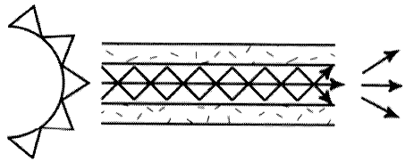

Fiber optic cable functions as a "light guide," guiding the light introduced at one end of the cable through to the other end. The light source can either be a light-emitting diode (LED)) or a laser.

The light source is pulsed on and off, and a light-sensitive receiver on the other end of the cable converts the pulses back into the digital ones and zeros of the original signal.

Even laser light shining through a fiber optic cable is subject to loss of strength, primarily through dispersion and scattering of the light, within the cable itself. The faster the laser fluctuates, the greater the risk of dispersion. Light strengtheners, called repeaters, may be necessary to refresh the signal in certain applications.

While fiber optic cable itself has become cheaper over time - a equivalent length of copper cable cost less per foot but not in capacity. Fiber optic cable connectors and the equipment needed to install them are still more expensive than their copper counterparts.

Single Mode cable is a single stand (most applications use 2 fibers) of glass fiber with a diameter of 8.3 to 10 microns that has one mode of transmission. Single Mode Fiber with a relatively narrow diameter, through which only one mode will propagate typically 1310 or 1550nm. Carries higher bandwidth than multimode fiber, but requires a light source with a narrow spectral width. Synonyms mono-mode optical fiber, single-mode fiber, single-mode optical waveguide, uni-mode fiber.

Single Modem fiber is used in many applications where data is sent at multi-frequency (WDM Wave-Division-Multiplexing) so only one cable is needed - (single-mode on one single fiber)

Single-mode fiber gives you a higher transmission rate and up to 50 times more distance than multimode, but it also costs more. Single-mode fiber has a much smaller core than multimode. The small core and single light-wave virtually eliminate any distortion that could result from overlapping light pulses, providing the least signal attenuation and the highest transmission speeds of any fiber cable type.

Single-mode optical fiber is an optical fiber in which only the lowest order bound mode can propagate at the wavelength of interest typically 1300 to 1320nm.
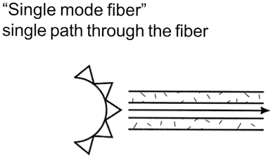

jump to single mode fiber page


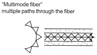
Multi-Mode cable has a little bit bigger diameter, with a common diameters in the 50-to-100 micron range for the light carry component (in the US the most common size is 62.5um). Most applications in which Multi-mode fiber is used, 2 fibers are used (WDM is not normally used on multi-mode fiber). POF is a newer plastic-based cable which promises performance similar to glass cable on very short runs, but at a lower cost.

Multimode fiber gives you high bandwidth at high speeds (10 to 100MBS - Gigabit to 275m to 2km) over medium distances. Light waves are dispersed into numerous paths, or modes, as they travel through the cable's core typically 850 or 1300nm. Typical multimode fiber core diameters are 50, 62.5, and 100 micrometers. However, in long cable runs (greater than 3000 feet [914.4 meters), multiple paths of light can cause signal distortion at the receiving end, resulting in an unclear and incomplete data transmission so designers now call for single mode fiber in new applications using Gigabit and beyond.


Monday, March 3, 2008

The Differences Between Hubs, Switches and Routers

Some technicians have a tendency to use the terms routers, hubs and switches interchangeably. One minute they're talking about a switch. Two minutes later they're discussing router settings. Throughout all of this, though, they're still looking at only the one box. Ever wonder what the difference is among these boxes? The functions of the three devices are all quite different from one another, even if at times they are all integrated into a single device. Which one do you use when? Let's take a look...

Hub, Switches, and Routers: Getting Started with Definitions

Hub
A common connection point for devices in a network. Hubs are commonly used to connect segments of a LAN. A hub contains multiple ports. When a packet arrives at one port, it is copied to the other ports so that all segments of the LAN can see all packets.

Switch
In networks, a device that filters and forwards packets between LAN segments. Switches operate at the data link layer (layer 2) and sometimes the network layer (layer 3) of the OSI Reference Model and therefore support any packet protocol. LANs that use switches to join segments are called switched LANs or, in the case of Ethernet networks, switched Ethernet LANs.

Router
A device that forwards data packets along networks. A router is connected to at least two networks, commonly two LANs or WANs or a LAN and its ISP.s network. Routers are located at gateways, the places where two or more networks connect. Routers use headers and forwarding tables to determine the best path for forwarding the packets, and they use protocols such as ICMP to communicate with each other and configure the best route between any two hosts

The Differences Between These Devices on the Network
Today most routers have become something of a Swiss Army knife, combining the features and functionality of a router and switch/hub into a single unit. So conversations regarding these devices can be a bit misleading — especially to someone new to computer networking.

The functions of a router, hub and a switch are all quite different from one another, even if at times they are all integrated into a single device. Let's start with the hub and the switch since these two devices have similar roles on the network. Each serves as a central connection for all of your network equipment and handles a data type known as frames. Frames carry your data. When a frame is received, it is amplified and then transmitted on to the port of the destination PC. The big difference between these two devices is in the method in which frames are being delivered.

In a hub, a frame is passed along or "broadcast" to every one of its ports. It doesn't matter that the frame is only destined for one port. The hub has no way of distinguishing which port a frame should be sent to. Passing it along to every port ensures that it will reach its intended destination. This places a lot of traffic on the network and can lead to poor network response times.

Additionally, a 10/100Mbps hub must share its bandwidth with each and every one of its ports. So when only one PC is broadcasting, it will have access to the maximum available bandwidth. If, however, multiple PCs are broadcasting, then that bandwidth will need to be divided among all of those systems, which will degrade performance.

A switch, however, keeps a record of the MAC addresses of all the devices connected to it. With this information, a switch can identify which system is sitting on which port. So when a frame is received, it knows exactly which port to send it to, without significantly increasing network response times. And, unlike a hub, a 10/100Mbps switch will allocate a full 10/100Mbps to each of its ports. So regardless of the number of PCs transmitting, users will always have access to the maximum amount of bandwidth. It's for these reasons why a switch is considered to be a much better choice then a hub.

Routers are completely different devices. Where a hub or switch is concerned with transmitting frames, a router's job, as its name implies, is to route packets to other networks until that packet ultimately reaches its destination. One of the key features of a packet is that it not only contains data, but the destination address of where it's going.

A router is typically connected to at least two networks, commonly two Local Area Networks (LANs) or Wide Area Networks (WAN) or a LAN and its ISP's network
. for example, your PC or workgroup and EarthLink. Routers are located at gateways, the places where two or more networks connect. Using headers and forwarding tables, routers determine the best path for forwarding the packets. Router use protocols such as ICMP to communicate with each other and configure the best route between any two hosts.

Today, a wide variety of services are integrated into most broadband routers. A router will typically include a 4 - 8 port Ethernet switch (or hub) and a Network Address Translator (NAT). In addition, they usually include a Dynamic Host Configuration Protocol (DHCP) server, Domain Name Service (DNS) proxy server and a hardware firewall to protect the LAN from malicious intrusion from the Internet.

All routers have a WAN Port that connects to a DSL or cable modem for broadband Internet service and the integrated switch allows users to easily create a LAN. This allows all the PCs on the LAN to have access to the Internet and Windows file and printer sharing services.

Some routers have a single WAN port and a single LAN port and are designed to connect an existing LAN hub or switch to a WAN. Ethernet switches and hubs can be connected to a router with multiple PC ports to expand a LAN. Depending on the capabilities (kinds of available ports) of the router and the switches or hubs, the connection between the router and switches/hubs may require either straight-thru or crossover (null-modem) cables. Some routers even have USB ports, and more commonly, wireless access points built into them.

Some of the more high-end or business class routers will also incorporate a serial port that can be connected to an external dial-up modem, which is useful as a backup in the event that the primary broadband connection goes down, as well as a built in LAN printer server and printer port.

Besides the inherent protection features provided by the NAT, many routers will also have a built-in, configurable, hardware-based firewall. Firewall capabilities can range from the very basic to quite sophisticated devices. Among the capabilities found on leading routers are those that permit configuring TCP/UDP ports for games, chat services, and the like, on the LAN behind the firewall.

So, in short, a hub glues together an Ethernet network segment, a switch can connect multiple Ethernet segments more efficiently and a router can do those functions plus route TCP/IP packets between multiple LANs and/or WANs; and much more of course.